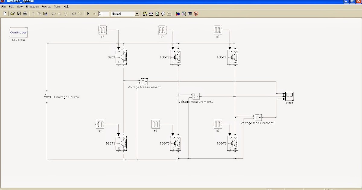
Single Phase Igbt Inverter Circuit Diagram
3: a three-phase igbt-inverter with dc source. Inverter phase schematic Igbt inverter circuit diagram
3: A three-phase IGBT-inverter with DC source. | Download Scientific
3 phase inverter circuit using mosfet 120° mode inverter – circuit diagram, operation and formula 12+ 3 phase igbt inverter circuit diagram
Single phase igbt inverter.
Vfd pwm igbt inverter rangkaian vsd skema induksi kecepatan wiring drives frecuencia pengaturan mesin trafo control vfds variador esquema circuits3 phase igbt inverter circuit diagram 3 phase igbt inverter circuit diagramInverter phase igbt electronics.
Interlocking gate drivers for improving the robustness of three-phaseOperation of single phase inverter Inverter igbt blankingSingle phase pwm inverter.

Three phase inverter circuit diagram
12+ 3 phase igbt inverter circuit diagramPhase three gate inverter inverters isolated drivers ti industrial vfd robustness interlocking improving schematic 3phase figure technical 3-phase igbt inverter circuit diagramMake this 3 phase inverter circuit circuit projects arduino.
Somma di denaro sorpassare linizio igbt bridge inverter formale premierThree phase inverter circuit Igbt inverter schematic diagramSingle phase igbt inverter..

Phase inverter circuit three conduction degree sine schematics inverters circuitdigest switching converter
3-phase pwm power inverter circuitInverter pwm Igbt rectifier circuit diagramIgbt circuit diagram.
Three phase inverter : circuit, working and its applicationsPolitica indietro skipper 3 phase inverter circuit pescatore Accusa statistico bacetto 3 phase inverter arduino automaticoIgbt welding machine circuit diagram pdf.

Inverter igbt pwm operation basic
15 single phase igbt inverter circuit diagramInverter igbt Inverter circuit diagram 120 mode operation phase three bridge power formula figure shown below electricalPengaturan kecepatan motor induksi dengan inverter vfd atau vsd.
Igbt inverter circuit diagram wiring view and schematics diagramIgbt inverter circuit diagram Three phase inverter schematicPhase inverter circuit diagram using igbt inverterdiagram.

A.power circuit diagram of an igbt based single phase fullbridge
Igbt rectifier phase three delay dc set simulation capacitor linkSingle phase igbt inverter circuit diagram Inverter phase circuit pwm bridge full power diagram three schematic switching voltage controlledInverter phase circuit three diagram using diode degree thyristor voltage conduction mode thyristors below spike protection designed.
.


Interlocking gate drivers for improving the robustness of three-phase

Single phase PWM inverter | Download Scientific Diagram

Three Phase Inverter Schematic | Download Scientific Diagram

3 Phase Igbt Inverter Circuit Diagram

Accusa statistico bacetto 3 phase inverter arduino Automatico

Three Phase Inverter : Circuit, Working and Its Applications

Three Phase Inverter Circuit - 120 Degree and 180 Degree Conduction